MECHANICAL REBAR SPLICE
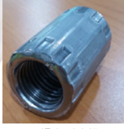
HS-BAR Rebar Coupler
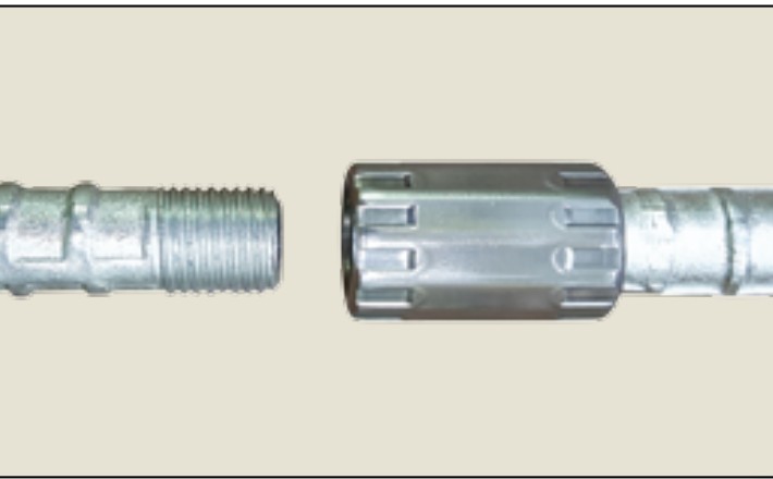
Bar ends are cold-upset to enlarge the section, roll-threaded and joined with a coupler. Korea's first — Ministry of Construction and Transportation New Technology No. 30.
WHAT IS HS-BAR
The upset-thread rebar splice
Mechanical splicing was developed over many years to meet the requirements of large reinforced-concrete structures and seismic design, and is now widely used on civil and building sites.
Manufacture — To raise the strength of the joint, the bar end is cold-upset (swaged) to enlarge its cross-section, a rolled thread (no metal removed) is formed, and the bars are joined by an internally threaded coupler.
Features — The ribs and lugs are upset over the thread length by the same rolling process used to make the bar, then roll-threaded; there is no incomplete thread, so clamping is excellent. The process was developed to simplify equipment and production, reduce labour and lower construction cost while securing superior quality.
ADVANTAGE
Advantages of HS-BAR
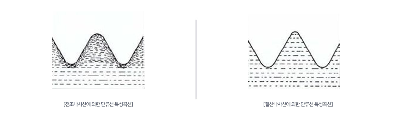
The decisive advantage: the bar is plastically worked (upset) before the thread is rolled, so the bar's properties are unaffected. Rebar has a fibrous grain flow created during rolling; a rolled thread keeps that grain flow continuous and dense, giving the thread very high strength.
01Safety
- Better bar spacing than lap splices; easier concrete placement
- Tensile or compressive strength of at least 125% of parent-bar yield strength
- Stress centres of both bars stay on the same axis — structurally very safe
02Economy
- Eliminates rebar lost to lap lengths (rising steel prices)
- Primary fabrication to site request — no secondary work
- Easy assembly reduces labour cost and schedule
03Constructability
- Advantageous for high-rise buildings and Top-Down, ILM and Pre-Fab methods
- Suits difficult second- and third-stage pours
- Visual inspection during assembly — precise work and easy checking
- Suited to members that must develop tension, keeping bar continuity
SPECIFICATION
Coupler specifications
Thread size, coupler outer diameter and length, and bar thread lengths (short thread S1 / long thread S2) by bar size. Unit: mm.
| Bar size | Thread | COUPLER | Bar thread length | ||
|---|---|---|---|---|---|
| O.D. | Length | Short (S1) | Long (S2) | ||
| D13 | M13 × 1.5P | 19 ±2 | 30 +2 | 15 | 30 |
| D16 | M16 × 2.0P | 23 ±2 | 38 +2 | 19 | 38 |
| D19 | M19.5 × 2.0P | 29 ±2 | 45 +2 | 22.5 | 45 |
| D22 | M22.6 × 2.5P | 34 ±2 | 50 +2 | 25 | 50 |
| D25 | M26.2 × 3.0P | 38 ±2 | 58 +2 | 29 | 58 |
| D29 | M29.6 × 3.5P | 43 ±2 | 65 +2 | 32.5 | 65 |
| D32 | M32.5 × 3.5P | 48 ±2 | 70 +2 | 35 | 70 |
| D35 | M36 × 4.0P | 53 ±2 | 75 +2 | 37.5 | 75 |
| D38 | M39.2 × 4.0P | 57 ±2 | 80 +2 | 40 | 80 |
| D41 | M42 × 4.0P | 60 ±2 | 86 +2 | 43 | 86 |
| D51 | M52 × 4.0P | 75 ±2 | 110 +2 | 55 | 110 |
Specifications may change for quality improvement. Coupler material: cold-forged from KS D carbon steel for machine structural use — SM40C, SM45C or 51B20, SM25C or better.
SPLICING METHODS
Standard splicing types
Three basic configurations cover most site conditions and construction methods.
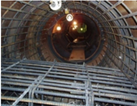
Short thread + short thread + coupler
The bar is rotated to engage. Applications: ILM, FCM, MSS, PSC-box bridge decks, slip-form columns, slabs and walls.
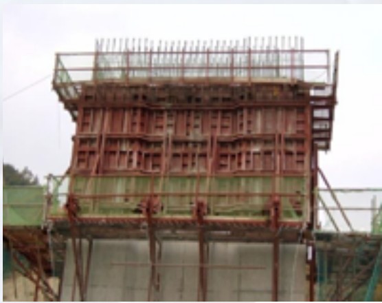
Short thread + long thread + coupler
One bar is threaded over the full coupler length and the coupler is rotated to engage. The most common type on civil and building sites. Applications: pre-assembly, RCD and other long bars.
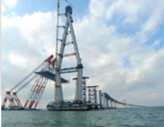
Short + long thread + coupler + lock nut
For pre-assembled cages in Pre-Fab construction; the coupler is made longer to absorb fabrication tolerance. Application: Pre-Fab method.
Special types SPECIAL TYPES
EWelding coupler
For fixing rebar to H-beams or other steel structures — the coupler is welded to the steel, then the bar is connected.
| D10 | D13 | D16 | D19 | D22 | D25 | D29 | D32 | D35 | |
|---|---|---|---|---|---|---|---|---|---|
| O.D. (D) | 17 | 19 | 23 | 29.5 | 34 | 38 | 43 | 48 | 53 |
| Length (L) | 11 | 15 | 19 | 22.5 | 25 | 29 | 32.5 | 35 | 37.5 |
Tolerance ±2 mm
GTerminator (anchorage) coupler
Replaces the hook at the bar end with an anchor plate that develops the bar without the development length.
| D13 | D16 | D19 | D22 | D25 | D29 | D32 | D35 | D38 | D41 | D51 | |
|---|---|---|---|---|---|---|---|---|---|---|---|
| A: O.D. Ø | 35 | 36 | 42 | 49 | 55 | 65 | 72 | 78 | 85 | 92 | 114 |
| B: thickness | 6 | 6 | 6 | 7 | 8 | 9 | 10 | 12 | 13 | 14 | 18 |
FForm Saver
The coupler is fixed to the formwork before the pour; after form removal the second-stage bars are connected.
| D10 | D13 | D16 | D19 | D22 | D25 | D29 | D32 | D35 | |
|---|---|---|---|---|---|---|---|---|---|
| O.D. (D) | 17 | 19 | 23 | 29.5 | 34 | 38 | 43 | 48 | 53 |
| Length (L) | 22 | 30 | 38 | 45 | 50 | 58 | 65 | 70 | 75 |
| Flange (Φ) | 62 | 62 | 62 | 62 | 62 | 82 | 82 | 82 | 82 |
| Thickness (T) | 1.7 | 1.7 | 1.7 | 1.7 | 1.7 | 1.7 | 1.7 | 1.7 | 1.7 |
Tolerance ±2 mm
HReducer · PC coupler
Reducer — joins bars of different diameters; the two internal threads are machined to different sizes.
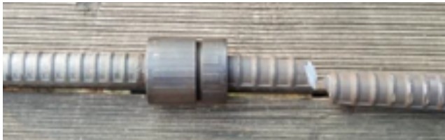
Coupler for precast concrete — designed for ever-larger PC elements. Fully compensates the misalignment of bars protruding from two PC members. Applications: Pre-Fab method, PSC structures, underground car parks.
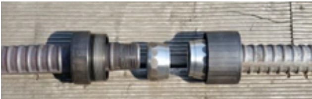
FIELD-ASSEMBLY COUPLER
U-type · UH-type field-assembly couplers
After years of development we commercialised a field-assembly coupler usable with SD600 rebar. Specially treated wedge segments and a body engage the parent bar to develop full structural performance (≥ 125% of yield), overcoming the weaknesses of earlier field couplers; anyone can install it easily.
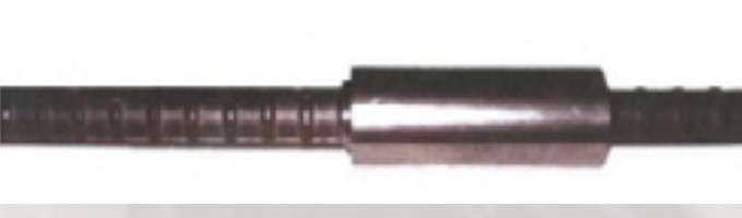
U-type dimensions mm · tolerance ±3%
| D10 | D13 | D16 | D19 | D22 | D25 | D29 | D32 | D35 | D38 | D41 | D51 | |
|---|---|---|---|---|---|---|---|---|---|---|---|---|
| A length | 52 | 63 | 82 | 98 | 111 | 128 | 143 | 159 | 174 | 185 | 196 | 225 |
| B O.D. | 23 | 30 | 33 | 36 | 42 | 45 | 50 | 55 | 60 | 65 | 70 | 85 |
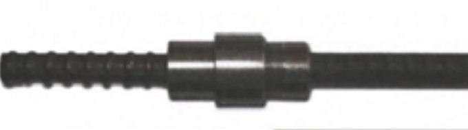
UH-type dimensions mm · tolerance ±3%
| D10 | D13 | D16 | D19 | D22 | D25 | D29 | D32 | D35 | D38 | D41 | D51 | |
|---|---|---|---|---|---|---|---|---|---|---|---|---|
| A length | 52 | 63 | 82 | 98 | 111 | 128 | 143 | 159 | 174 | 185 | 196 | 225 |
| B O.D. | 30 | 36 | 38 | 45 | 50 | 55 | 60 | 65 | 70 | 75 | 80 | 95 |
U-type installation
- Remove the wedge segments supplied inside the body.
- Fit the segments to both bar ends, sloped side towards the bar end, aligning the segment grooves with the bar lugs so the two segments sit as parallel as possible (rotate a segment 180° to adjust).
- Slide the body over the fixed bar (e.g. the bar cast in concrete) and turn to engage.
- Insert the connecting bar into the other end of the body and turn the bar to engage.
- Finally tighten the connecting bar with a pipe wrench; the fixed-bar side locks completely too.
UH-type installation
- Remove the wedge segments supplied inside the body.
- Fit the segments to both bar ends as for the U-type (slope towards the bar end, grooves aligned with lugs, segments parallel).
- Engage the segments with the long-thread body and the short-thread body.
- Turn the outer body fully onto the long-thread body.
- Connect the short-thread body and tighten the bar with a pipe wrench.
QUALITY CONTROL
Quality control · testing
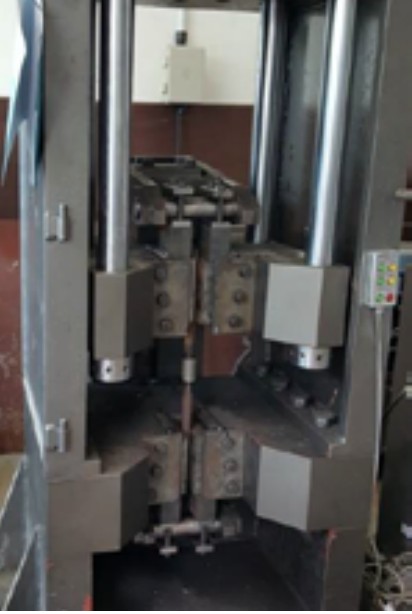
Test method: KS D 0249 (test methods for mechanical splices). Threading: the bar lugs and ribs are upset into a round section, the end is faced, a thread is rolled and the bar is joined by a tapped (internally threaded) coupler — a mechanical splice.
Mechanical property tests KS D 3504
| Item | SD 300 | SD 400 | SD 500 | SD 600 | SD 400S | SD 500S | SD 600S |
|---|---|---|---|---|---|---|---|
| Yield strength (N/㎟) | 300–420 | 400–520 | 500–650 | 600–780 | 400–520 | 500–620 | 600–720 |
| Tensile strength | ≥ 1.15 × yield | ≥ 1.15 × | ≥ 1.08 × | ≥ 1.08 × | ≥ 1.25 × | ≥ 1.25 × | ≥ 1.25 × |
Types of test
- Appearance — no substances on coupler or threaded bar that reduce concrete bond; bar end faces flat for tight seating
- Visual inspection — 100% of incoming couplers checked for oil, dirt etc.; bar threads checked for cleanliness, end flatness, straightness and cold working
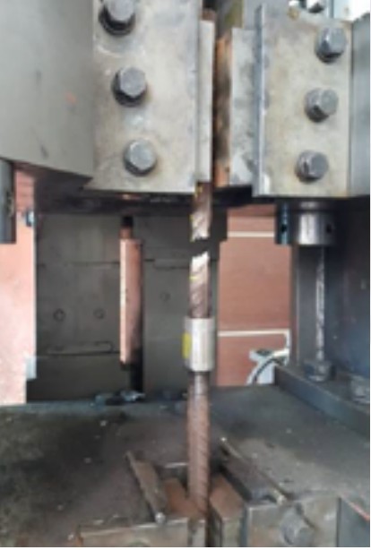
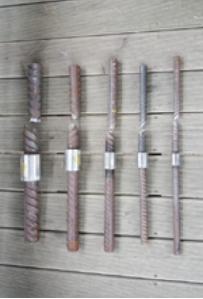
- Tensile test (monotonic) — yield and tensile strength per KS B 0802 (area per KS D 3504)
- Low-cycle test — 100 cycles between 5% and 90% of bar yield, then tension to fracture (Korea Expressway Corp. mechanical splice QC standard, April 2002)
- High-stress cyclic test — static test procedure repeated 30 times; stiffness change and maximum deformation recorded
- Static strength test — load to 95% of yield, unload to 2%, measure axial stiffness and residual deformation, then tension to fracture
- Low-temperature test — held 15 min at −120 ℃ in liquid nitrogen gas, then tensile test; the threaded joint must not fracture
- High-cycle fatigue — sine-wave load between 3 and 13 kgf/㎟ at 3–10 Hz for 2 million cycles; residual deformation and fracture checked
Applicable standards STANDARDS
- KS D 0249
- Test methods for mechanical splices of reinforcing bars
- KASS
- Korean Architectural Standard Specification (MOCT)
- KS
- KS B 0802 tensile testing of metallic materials · KS D 3504 steel bars for concrete reinforcement · KS D 3517 carbon steel tubes for machine structural purposes · KS D 3752 carbon steels for machine structural use
- ASME Sec. III
- RCD pre-assembly, Yeonyuk Bridge 1 (HD51) · Incheon LNG connecting bars (HD35, HD51) · ILM diaphragm · building pre-assembly · World Cup stadiums (Gwangju, Suwon) · tie bars · welding couplers
Standards apply partially, as referenced by the project specification. Copies of test reports (KICT etc.) are provided on request.
MANUFACTURING
Thread-forming and coupler-socket production
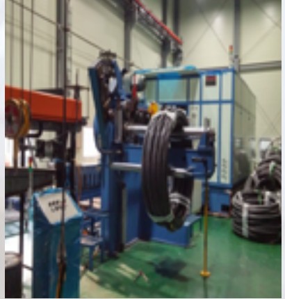
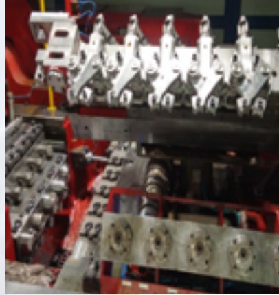
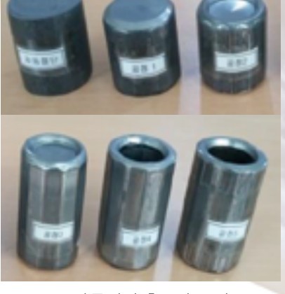
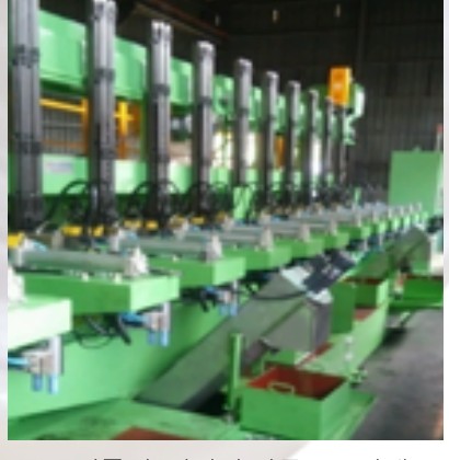
Bar threading is a semi-automatic line — upsetting press → end-facing machine → thread roller → handling line — producing up to D51. Coupler sockets are cold-forged from bar stock on a former and tapped automatically.
Rebar upset threading REBAR THREADING
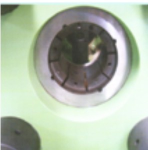
Roller-type upsetting up to D51; semi-automatic.
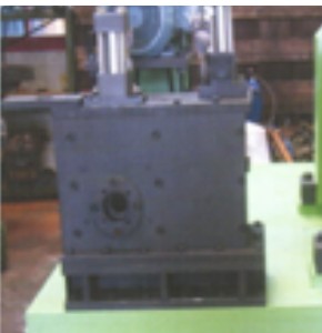
Removes irregularities from cutting and upsetting so the thread can be rolled cleanly.
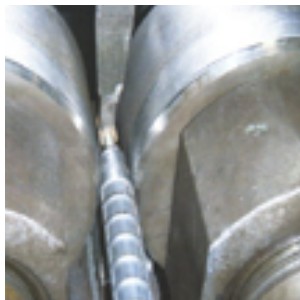
Thread formed by rolling dies; semi-automatic.
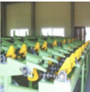
Channel conveyors move bars between stations; semi-automatic.
Coupler socket production COUPLER SOCKET