TUNNEL & GROUND SUPPORT
Tunnel & Ground Support
Rock bolts, steel fibre and removable soil nailing — materials that hold the ground in tunnels and excavations, produced in-house to KS-certified quality.
ROCK BOLT · KS E 3132
Rock bolt, all-screw type
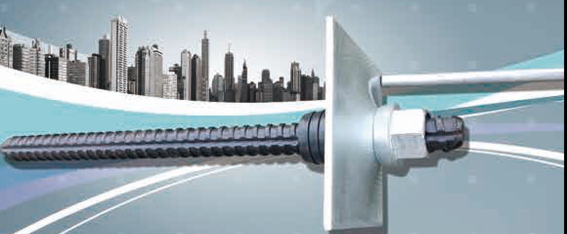
Rock bolts and components for NATM tunnel rock support, produced under Korean Industrial Standard KS E 3132 certification No. 99-0650. The thread runs the full length (all-screw), so a nut can be fitted at any position.
Mechanical properties KS E 3132
| Diameter | Yield point | Ultimate tensile strength | Elongation | Test standard |
|---|---|---|---|---|
| 25 mm | ≥ 350 kg/㎟ | ≥ 490 kg/㎟ | ≥ 18% | KS E 3132 (rock bolts and components) |
Dimensions and unit mass
| Size | Unit mass (kg/m) | Nominal dia. (mm) | Nominal area (㎟) | Pitch p (mm) | Thread height a (mm) |
|---|---|---|---|---|---|
| D25 | 3.98 | 25.4 | 5.067 | 12 | 2.0 |
| D29 | 5.04 | 28.6 | 6.424 | 14 | 2.0 |
All-screw thread · pitch 12 mm, thread height 2 mm ± 0.3 mm
Advantages
- A nut can be fitted at any position along the bolt.
- Bolts can be joined end to end with sleeves to any length.
- The bolt end is pre-finished so the nut runs on easily.
Accessories ACCESSORIES
| Item | Material · size | Notes |
|---|---|---|
| Ring nut | KS B 1012 SS400 | Hot-forged, excellent mechanical properties. Nut and ring washer combined with a threaded interior — saves material, easy installation, maximum clamping over a short length. KT mark |
| Hex nut | KS B 1012 SS400 | Machined from hexagonal bar |
| Domed plate | for Ø25 · d Ø40±3 · h1 20±5/30±5 · ℓ 150/120 · t 6/9/10/12 | Made to order |
| Flat plate | for Ø25 · d Ø30±3 · ℓ 150/120 · t 6/9/10/12 | Made to order |
| Double plate | H-beam 250: L500 H350 t10 · H-beam 300: L550 H400 t12 | Made to order |
| Sleeve | hex 42 × 38 × L150 · bore 25 | For joining rock bolts |
| Cast plate | D Ø32±3 · B 168±5 · H 40±5 | Grout inlet and outlet holes |
| Expansion shell | — | Anchors the rock bolt in the rock. Usable in varied ground, effective in dry or wet rock, spring prevents dislodging; grout injected after fixing. |
INDICATOR
Protective caps and indicator rods for rock bolts and soil nails
Our rock-bolt indicator rod makes installed bolts visible even after shotcrete, so supervisors can verify installation at a glance.
- Low cost.
- Simple to install.
- Bolt installation can be verified after shotcreting.
- As the bolt manufacturer we can reconcile indicator count with bolt deliveries.

HS STEEL FIBER
Steel fibre for concrete reinforcement
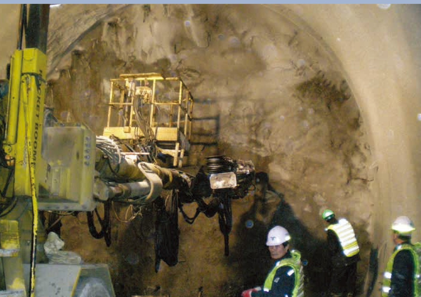
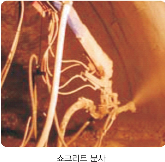
HS Steel Fibre is already used in tunnel shotcrete across Korea and recognised for its quality. Fibres disperse evenly through the concrete so strength is uniform everywhere, turning brittle behaviour into ductile behaviour and improving durability.
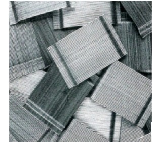
Hooked ends
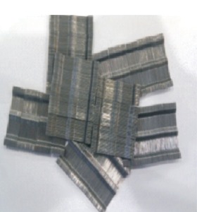
Centre embossing
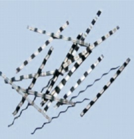
Single type
Product range
| Product | Size | Packaging |
|---|---|---|
| HSSF01 · 02 | 30 mm × Ø0.5 | 20 kg bags · 1 t bulk bags |
| 35 mm × Ø0.7 | ||
| HSSF03 | 0.37T × 1.0W × 30 mm |
Other sizes made to order.
Technical data Ø0.5 × 30 mm, hooked ends
- Material
- ASTM A820 Type 1
- Length / diameter
- 30 mm (1.18 in.) / Ø0.5 (0.0276 in.)
- Shape
- Hooked ends · clean bright steel
- Tensile strength
- ≥ 1,044 N/㎟ (700–1,200 MPa)
- Aspect ratio
- ≥ 60
- Features
- High aspect ratio gives strong bond to concrete · cold-drawn at room temperature
Features of HS Steel Fibre
- No balling during mixing or placing — easy to batch
- Increases tensile, shear, toughness and impact strength of concrete
- Very high tensile strength — excellent crack control
- Can replace rebar or mesh depending on the works
- Made to KS (ASTM) standards
- Strict quality control; several fibre types available
- Prevents the voids that form behind wire mesh in shotcrete — full adhesion
Shotcrete mix guidance
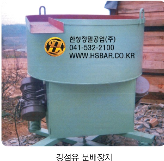
- Add fine aggregate and fibre while mixing → add sand and cement → add water → mix one more minute after fully blended
- Fibre dosage 40–45 kg/㎥ standard (adjust to flexural-toughness tests)
- W/C ≤ 50%, max. aggregate 13 mm, fine-aggregate ratio ≥ 65%
- Cement content typically 400–500 kg/㎥ · accelerator 5% of cement by mass (standard)
Applications
| Tunnels | Follows the excavated profile (material saving) · leak prevention · longer life |
|---|---|
| Pavements | New roads, runways · crack control · factory floors · fatigue resistance · lower repair cost · thinner slabs |
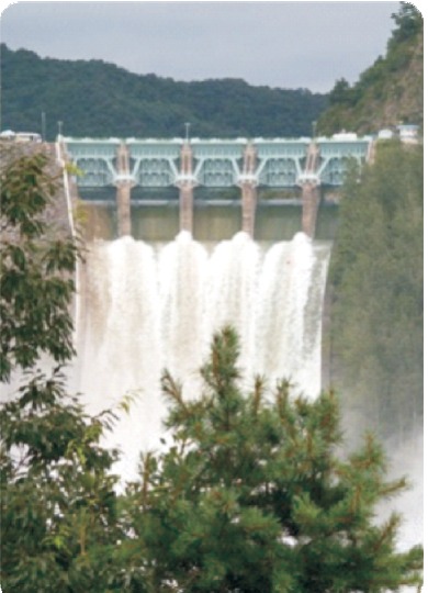
| Dams · breakwaters | Lighter sections · longer life · crack control (heat of hydration) · no steel reinforcement · abrasion resistance |
| Elevated roads · bridge decks | Fatigue and abrasion resistance · thinner overlays |
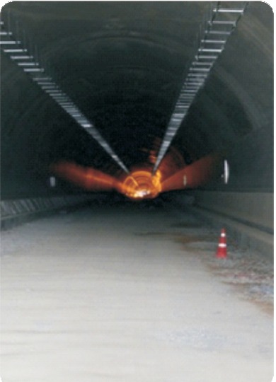
REMOVE SOIL NAILING METHOD · NEW TECHNOLOGY No. 257
Removable Soil Nailing method
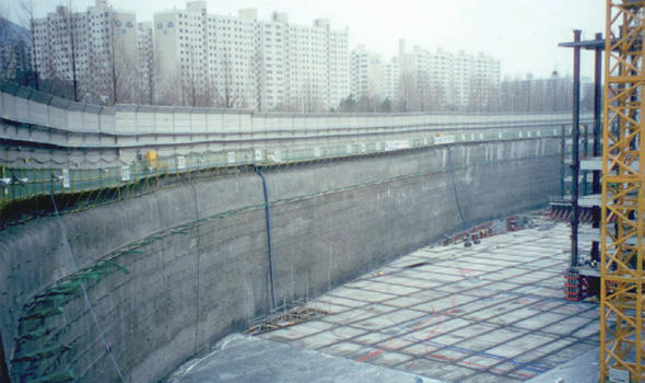
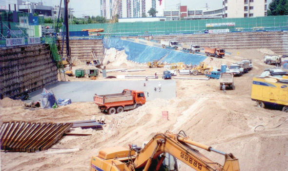
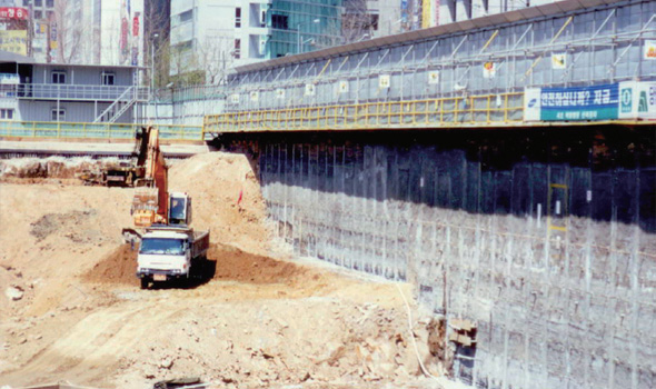
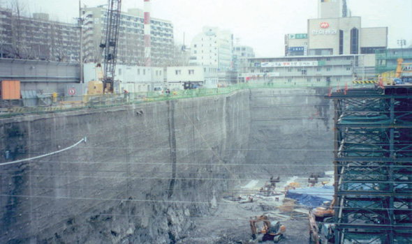
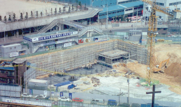
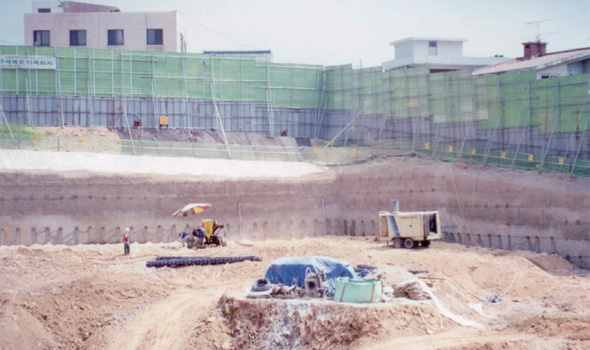
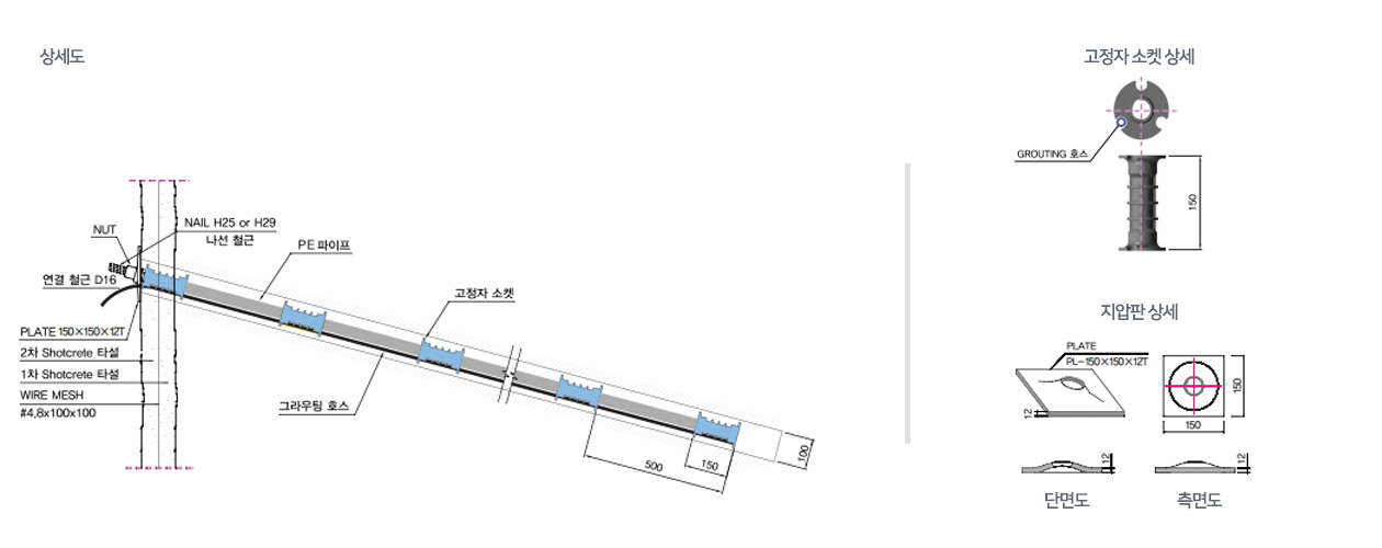
For temporary vertical excavation walls, fixing sockets and PE pipe separate the threaded bar from the cement grout so it functions like a conventional nail — then, after excavation and the basement wall are complete, the bar is removed, leaving the ground free for future construction.
System components
- D25 / D29 threaded bar (rock bolt), SD350 or higher to KS D 3504
- PE pipe separating the bar from the cement grout
- Fixing socket bonding the nail to the grout and acting as spacer
- Bearing plate and nut fixing to the outer wall
Pull-out behaviour
In conventional soil nailing the grout and bar act as one, so skin friction concentrates near the nail head. In the removable system the grout and bar are united only at the fixing sockets, so skin friction peaks at each socket and decreases away from it. Socket spacing (500 / 1,000 mm) tunes the pull-out response to the design.
Features
- Fixing sockets and PE pipe allow the nail to be 100% removed.
- Nails are reused — minimal waste of resources.
- No corrosion, low environmental risk.
- Removal after completion helps resolve neighbour disputes.
- Land-use fees apply only for the temporary period — economical.
- No underground obstruction for future works — improves the subsurface environment.
- Ground–nail interaction is well understood, so over- or under-design can be predicted and adjusted.
Procedure PROCEDURE
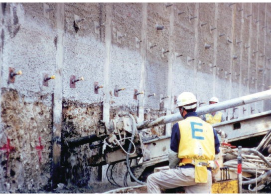
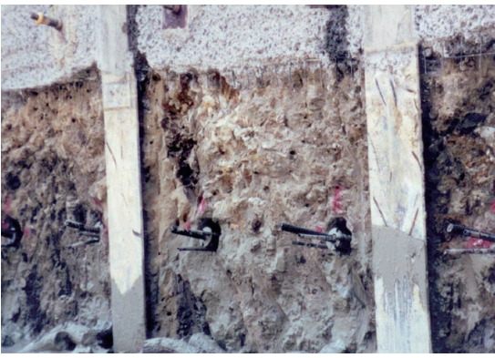
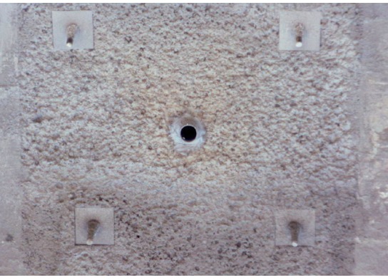
After shotcrete
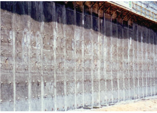
References REFERENCES